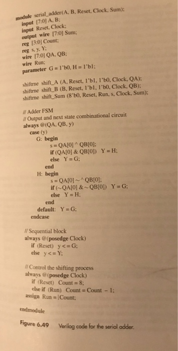
Verilog Code For Serial Adder Register
I am supposed to create 4 bit full adder verilog code in vivado.But when I try to test in the simulation.It give me z and x output.Which part of code I have to change to get an output in simulation module myfulladder( input A, input B, input CIN, output S, output COUT ); assign S = A^B^CIN; assign COUT = (A&B) (CIN&(A^B)); endmodule This is the one bit full adder verilog code I have check the schematic for this code and everything is correct. Module fourbitadder( input 3:0 A, input 3:0 B, input C0, output 3:0 S, output C4 ); wire C1,C2,C3; myfulladder fa0 (A0,B0,C0,S0,C1); myfulladder fa1 (A1,B1,C1,S1,C2); myfulladder fa2 (A2,B2,C2,S2,C3); myfulladder fa3 (A3,B3,C3,S3,C4); endmodule Test bench module test4bit( ); reg 3:0 A; reg 3:0 B; reg C0; wire 3:0 S; wire C4; fourbitadder dut(A,B,C0,S,C4); initial begin A = 4'b0011;B=4'b0011;C0 = 1'b0; #10; A = 4'b1011;B=4'b0111;C0 = 1'b1; #10; A = 4'b1111;B=4'b1111;C0 = 1'b1; #10; end endmodule.
Oct 23, 2010 Verilog Serial Adder in Behavioral Description. All variables and given/known data My homework is to design a Serial Adder in Verilog using a shift register module, a full adder module, and a D Flip-Flop module. I know my full adder and flip flop modules are correct, but I am not so sure about my shift register. Code (Text): //Shift. Jan 26, 2013 - verilog code for Full adder and test bench. Module fa(a, b, c, sum, carry). Creamware pulsar 2.
I'm guessing you wrote your code in word editor (ex Microsoft Word. I also noticed you used and assign statement on the reg type temp. Design a serial adder circuit using Verilog. The circuit should add two 8-bit numbers, A and B. The result should be stored back into the A register.
.
This repository contains behavioral code for Serial Adder.The following individual components have been modeled and have been providedwith their corresponding test benches:
- Parrallel Input Serial Output Shift register (PISO) (
piso.v) - D Flip Flop (
d_flipflop.v) - Full Adder (
full_adder.v)

File serial_adder.v is the master node, the corresponding testbench isserial_adder_tb.v. To compile and visualise the waveforms (using iverilogand gtkwave), follow these steps:
- Install
iverilogandgtkwaveusing the instructions given here. - Clone this repository using the command
git clone https://github.com/RJ722/serial-adder-verilog. cd serial-adder-verilogiverilog -o serial_adder.out serial_adder_tb.v./serial_adder.outgtkwave serial_adder_tb.vcd # Visualise waveforms
For changing the input values to the adder, please make changes in serial_adder_tb.v.